Method for Producing Injection-Stretch-Blow Moulded Bottles and Jars with a Microcellular Foamed Structure
A complex product strategy to achieve product protection, environmental protection, consumer protection, reclosability, consumer convenience and sustainability
1. Preface
Injection-stretch-blow moulded bottles and jars, subsequently referred to as containers/articles, are in constant demand on the market due to the fact that they reduce container weight with consequent container cost savings.
High market demand has resulted in containers with marginal mechanical properties of insufficient stiffness.
Containers with a microcellular foamed internal structure based on gas expansion have none of these disadvantages.
On the contrary, containers having this foamed structure offer the following advantages:
- Weight and polymer reduction, due to the fact that gas weighs almost nothing
- Increased mechanical properties (specifically higher stiffness )
- Significant reduction in cycle time
The subject of this study is the advantages and method of manufacturing a container with a microcellular foamed internal structure having the added advantage of a compact surface.
This technology has not been executed , therefore the described process is of theoretical nature.
2. History of injection-moulding technology applied to physical foaming polymers
Foam-injection moulding technology was developed prior to the millennium. It was invented by the Massachusetts Institute of Technology (MIT) and was subsequently developed by the company Trexel Inc. in Wilmington, Mass. into an industrial process going under the brand name of MuCell.
3. Physics of foaming
There are two methods whereby propellants are used to give polymers a foam structure:
A) Chemical propellants
Azodicarbonamide (ADC) dominates the world market with 88%. It is applied in shoe soles, cross-linked PE and PVC. However, all these chemical propellants trigger decomposition processes cannot be tolerated for food containers and packaging.
B) Physical propellants
These are gas fluids which are added to the polymer melt and lead to a foaming-process that provides a microcellular structure. The fluids can be butane and pentane gases but recently the inert gases nitrogen (N2) and/or carbon dioxide (CO2) have become the leading gases used.
4. Benefits of foaming polymer melts
The benefits fall into two categories: article and process advantages.
A) The article advantages mainly stem from the increase in wall thickness due to the foam structure. This produces an article with significantly higher mechanical properties (stiffness). Furthermore, the foaming effect leads to weight reduction and lower polymer consumption due to the negligible weight of gases.
B) The process advantages accrue from viscosity reduction of the melt. This results from a liquid propellant being mixed into the melt. Consequently, the injection pressure can also be reduced and less clamping force is required. In addition, gas pressure expansion filling the mould cavity will cut down the secondary injection pressure time and sink marks will be compensated. Furthermore, the liquid propellant changing into a gas phase during the moulding process offers the advantage of inherent cooling and will lead to a reduction in cooling time.
5. Processes for manufacturing containers with a microcellular foam-structure
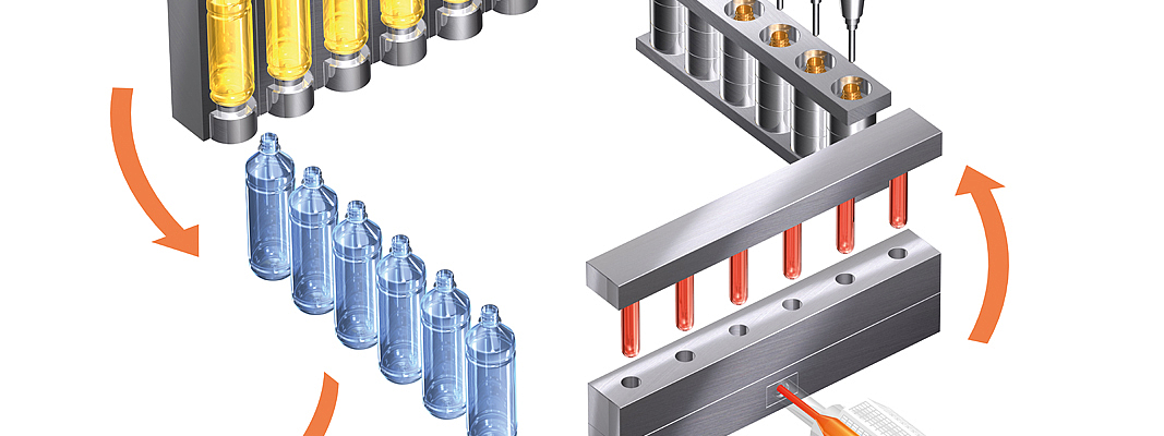
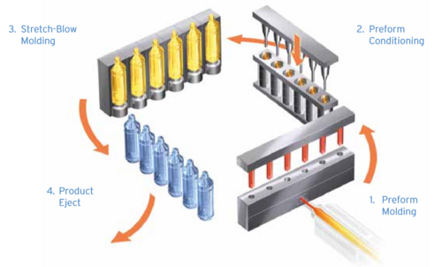
5.1 Manufacturing containers by integrated 1-step process machine (fig. 2)
- Injection station: Preforms are injected and cooled to the temperature of the polymer where it can be stretched-blow moulded. Here the liquide nitrogene (N2) will be injected into the melt , which will be explained in capt.5.2
- Conditioning station: Here the preform will be given a special heatprofile to influence the wallthickness-distribution in the later-on stretch-blow moulded container.
- Stretch Blow Moulding Station: The preform will be stretched axial and simutaneous inflated by airpressure against the blow-mouldwall to form a container.During this process the molecule-chains of the polymer will be biaxial oriented in the direction stretch and circumferencial blow. This gives the container higher physical performances.
- Container Take-Out: The containers are ejected
5.2 The MuCell Process to allow polymers to be foamed with an inert gas
The MuCell Process was developed by MIT in Boston and later brought to an industrial standard by Trexel Inc. USA. This process allows for all polymers to be foamed with an inert gas (N2 or CO2). The gas cells in the final article are large in number but having a cell dimension of 5 up to 50 um. This technology has achieved the highest level of market success for foaming polymers.
The manufacturing stages of the MuCell foaming process are as follows:
- Melting and homogenizing the polymer in the injection unit
- Precise gas injection (N2 or CO2) under pressures of 100 up to 200 bar into the injection cyl.
- Complete dissolving of the gas in the melt in the mixing zone of the injection-screw, whilst setting the melt under backpressure to avoid pre-foaming.
- Injecting the melt into the mould under high velocity by using a hydro booster and inducing a thermodynamic instability that leads to nucleation
- Growth of micro-cells in the injection mould by means of gas expansion.
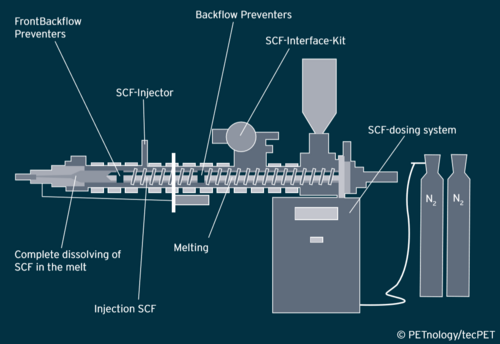
Physical foaming necessitates a special injection unit with additional components:
- A screw incorporating a gas mixing zone and hence of longer construction ¡ An injection cylinder that requires a gas injector
- A gas unit for compression to pressure levels of 100 to 200 bar plus liquid gas dosing
- Software to control the process of gas injection in the injection-unit
- A hydro booster for high injection velocities so as to achieve a homogeneously fine cell structure in the core and compact sidewalls
- A specially designed injection-screw that has a mixing zone and two backflow preventers near the gas injector so as to avoid backward foam activities.
The characteristic of this MuCell Process is that the fluid gas is dosed in a Super Critical Fluid (SCF) condition, thereby producing a mono phase mixture of polymer melt and liquid gas.
Variables on the foam structure (density reduction, cell dimensions and cell distribution), such as melt temperature, injection velocity, gas dosage and mould temperature, influence each other. Under higher melt pressure more liquid gas can be dissolved. Consequently, back pressure has to be applied to the melt. The concentration of liquid gas is between 0.3 and 1 % N2. CO2 is seldom used since it leads to much larger cell structure and less fine distribution.
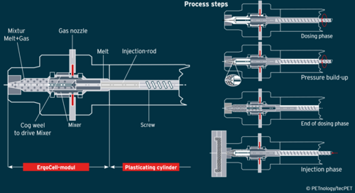
5.3 Alternatives to the MuCell Process (see fig. 4)
Ergocell Process
The Ergocell Process developed by Sumitomo, Japan and DEMAG Plastics’ Machinery Germany functions in a similar way to the MuCell Process: a fluid gas in supercritical condition is mixed into the polymer melt. The difference is the point of mixing.zone. The Ergocell dosing unit is mounted at the tip of the injection barrel in place of the barrel nozzle. The advantage of this is that a standard machine can be retrofitted. As with MuCell, liquid gas injection is undertaken during plastification. The liquid gas is dosed by an injector and distributed by a dynamic mixing element in the polymer melt. This mixing element is connected to and d riven by the screw. The mono phase polymer gas solution is put under pressure by activating the backpressure until melt injection is initiated.
6. Applying the conditioning station for additional foaming in order to achieve higher wall thickness
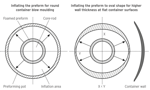
The conditioning station offers the unique advantage of extending the outside diameter of the preform by prefoaming in order to achieve higher wall thickness of the blown container.
This can be achieved by driving the preform into a pot ( additional foaming pot ) which has a wider outside diameter than the preform itself. The inside diameter of the preform should be controlled by driving a core-rod into the preform which is almost identical to the shape of the injection core. Otherwise the inside diameter of the preform will also foam and reduce it to an uncontrollable shape making it impossible to apply the stretch rod.
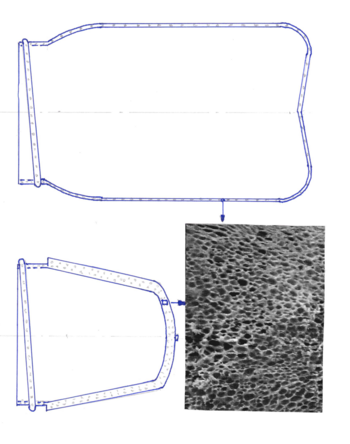
As for oval or rectangular containers the prefoaming pot can be ellipse shaped at the corresponding preform zones where increased container-wallthickness is desired. These ellippse shaped preforms having at corresponding areas higher wall thickness will then be blown into the flat surfaces of the non-round blow mould subsequently providing a higher wall thickness at the flat container zones (fig. 5).
7. Influence of the blowing pressure on the foam structure of bottles and jars
All studies concerning MuCell technology were made on injection moulded articles. There is no practical experience of the blow pressure effect on the cellular foam structure of containers made by single stage injection stretch-blow moulding technology.
In theory, blow pressure reduces the cellular foam structure to a pressure equivalent to the blow pressure and internal cell pressure of the N2 gas.
Should the blow pressure significantly reduce the foam structure in the bottle/ jar, an intelligent blow sequence has to be developed, reducing the blow pressure to a minimum when the inflated preform touches the blow mould-wall.
8. Preform mould design
The hot runner system has to be symmetrically balanced. Otherwise small differences in the length of the hot runner to the individual cavities will result in different cell structure (foam) levels because of different residents times and consequently different article weights.
In order to avoid uncontrolled melt prefoaming near the gate area, the cavity should be equipped with a needle-valve. This opens and closes hydraulically.
9. Applications for bottles/jars having a cellular foam structure
The classical market for transparent PET bottles will not be the target for foamed bottles /jars for aesthetic reasons: the cellular foam structure does not show the liquid contents (beverages, mineral water, edible oil) to advantageous effect. The target market will be exclusively coloured bottles/jars for detergents, shampoos, creamy food, etc., where the foam-structure can’t be seen.
10. Advantages of containers having a cellular foam- structure
A) Weight and polymer savings can be up to 35% at injection moulded articles. Consequently, foamed containers (bottles/jars) will target the market for classical extrusion blown PE containers by offering a better article price.
B) Improved mechanical properties, namely greater stiffness due to the higher wall thickness. This advantage can be used to achieve additional weight reduction, thus offering advantages in article prices.
C) Shorter cycle times. These can be achieved because less polymer has to be cooled down to blow temperature while the secondary injection pressure time is reduced due to the fact the internal gas pressure in the cells will fill the injection-cavity. These shorter cycle times will lead to more attractive prices for the moulded containers.
11. Applying this technology to Two-Stage-Processes
This technology is applicable to single stage injection stretch-blow moulding operating with rotary or linear functioning processes. In Two-Stage Processes a preform with a cellular foam structure has to be reheated. Due to the residual gas pressure inside the cells, the preform will expand during reheating to a non- functional shape and will not lead to homogeneous container quality. The same applies to one and a half stage manufacturing processes such as PF Machines.
12. The patent situation
Eberhard Neumann has filed a patent application with the German Patent Authorities. This patent-application has been published under file-Nr : DE 10 2017 003 227 A1
The comPETence center provides your organisation with a dynamic, cost effective way to promote your products and services.
magazine
Find our premium articles, interviews, reports and more
in 3 issues in 2026.
